Tuesday, May 17, 2016
Monday, May 9, 2016
May 9, 2016
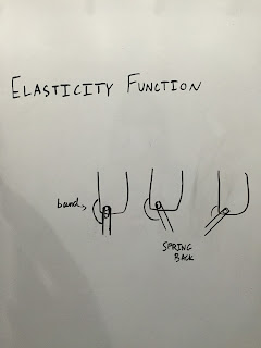
Elastic, no-tie shoelaces will be used for the elasticity function.Tightened in the front, they will keep the bands on the correct sides of the brace. Our next step is to finalize our poster for the Stem Symposium.
Wednesday, April 27, 2016
April 27, 2016
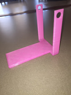
The flexible insole section has printed and fits well with the calf section. We realized that we needed to 1. work on a method (cap) to keep the side attachments secure to the pegs and 2. construct a groove or a hole in the pegs so that the rubber bands stay in the correct place.
By drilling a hole into the pegs, we were able to feed the rubber band through all three holes. This design succeeds in both connecting the sections so the attachments don't come apart and keeping the rubber band on the correct side of the peg so that it lifts the insole section in the right direction.
By drilling a hole into the pegs, we were able to feed the rubber band through all three holes. This design succeeds in both connecting the sections so the attachments don't come apart and keeping the rubber band on the correct side of the peg so that it lifts the insole section in the right direction.
Monday, April 25, 2016
April 25, 2016
We will be printing our insole section in a filament that is a little flexible and our calf section will remain in the hard plastic material for now. After testing the elasticity function with a rubber band, we found that there was difficulty keeping the insole section attached to the calf section on the left side. We will either get rid of the left-side attachments, or we will find pegs to keep the brace secure.
Tuesday, April 19, 2016
April 19, 2016
The brace fits inside of the shoe and works well while walking. Our next steps are to experiment with different printing materials and incorporate the elasticity function with a rubber band.
Friday, April 15, 2016
April 15, 2016
Today, we are editing our device further - with the attachments that connect to the middle of the insole, the device does not fit into the shoe, so we will connect them perpendicularly. This will allow for the device to fit into the shoe and to also print correctly, without excess plastic inhibiting functionality.
Thursday, April 7, 2016
April 7, 2016
Today, we designed the updated insole section. We will have this as well as the calf section printed. We also have reached out to schedule another meeting with Dr. Matt Caster. In addition, we discussed our project expectations for the rest of the year. These constructing a final brace that fits inside of the shoe, is usable, includes the elasticity function, and experiments with different filaments.
Wednesday, March 30, 2016
March 30, 2016
Today, we added attachments into our product to incorporate the elasticity function. For a rough idea of how this will work, we can cut two rubber bands so that we have elastic "strings" for both sides of the brace. We can then feed one band through the holes on either side and tie them securely. This will create tension when the foot is back, causing it to help the user swing their foot forward which follows with the release of the tension. The individual's using this brace are capable of pushing off by themselves but cannot lift their toes up, so this design will be useful.
Our next step is to again use the Boolean Union function to create one solid part from the two splines and foot insole. In MeshMixer, we will make sure the part is as durable, stable, and symmetrical as possible. Then, we will print out the two parts and test our brace.
Our next step is to again use the Boolean Union function to create one solid part from the two splines and foot insole. In MeshMixer, we will make sure the part is as durable, stable, and symmetrical as possible. Then, we will print out the two parts and test our brace.
Thursday, March 10, 2016
March 10, 2016
After presenting at the TechShop on March 8, 2016, we were able to get feedback and suggestions on our project. These suggestions includ using softer material for the insole and connecting the elastic band through two holes extending off the calf sections to the insole section. The feedback throughout the presentation was positive. Additionally, a person with marketing experience told us that we could eventually mass produce these products for a substantial profit if we were able to.
Wednesday, March 2, 2016
March 3, 2016
The completed poster to accompany our presentation at Tech Shop on March 8th can be found below and in "Design Process".
March 2, 2016
We used the Boolean Union feature on MeshMixer to create one solid out of the left and right attachments and the custom insole. Because this is a custom product, the dimensions of the insole as well at the attachments will differ per person. The dimensions for this particular spline attachment are: X: 4 in. Y: 0.95 in. Z: 5.381 in. We can now think about whether it would be more effective, secure, and/or comfortable with one or both attachments. We can make further adjustments as we test out different designs.
Also, an idea for the elasticity function could be to have snap-on attachments that connect to each section of the brace with an elastic band in between and the strength can be adjusted by snapping on the pieces closer together or farther apart.
Also, an idea for the elasticity function could be to have snap-on attachments that connect to each section of the brace with an elastic band in between and the strength can be adjusted by snapping on the pieces closer together or farther apart.
Tuesday, March 1, 2016
March 1, 2016
Today, we started designing our poster to accommodate our presentation at TechShop on March 8. The insole to calf attachment was also printed (see below). We mirrored this design on Inventor so that we now have an attachment for both sides of the brace. For our custom insole, another group, Lynne and Joan, has given us their file which we will combine to the two attachments to form one solid (Boolean Union feature on MeshMixer).
 |
| AFO w/ Printed Insole Attachment March 1, 2016 |
Wednesday, February 24, 2016
February 24, 2016
We adjusted the attachment so that the spline is approximately 2 inches shorter. Currently, without the adjustment, the attachment will not fit into the shoe correctly. We will continue to test the prototype and make further corrections. We will also scan Naomi's foot and create an insole from the scan using MeshMixer which we will then join with the attachments to make one solid (this will be the second part of the brace). After we complete the brace structure prototype, we will add on the elasticity function (our plans for this can be found under "City As Our Campus Mentor Info"):
- an elasticity cable connecting from the calf section to the bottom/foot section (on the outside) that doesn’t have resistance when foot is forward but then snaps into position when foot is back, tension will break during swing phase of the gait cycle
Monday, February 22, 2016
February 22, 2016
Today, we began designing the pieces to attach the insole to the calf section. We will use this attachment, created in Inventor, and transfer it into MeshMixer to conjoin the sections.
We will perfect this piece and then decide if we will need just one or two of these pieces, taking stability into account. We can use this one to test on the outside of the brace on the left foot or the inside of the brace on the right foot. If we decide we want an attachment on both sides of the foot, we will need to either mirror this part or construct a separate one. Then, with Boolean Union, we can join the soon-to-be-created insole with the attachment into one solid. After we finish this section of the brace, we will work on the elasticity function.
Thursday, February 18, 2016
February 18, 2016
Today, we visited TechShop, http://www.techshop.ws, to learn how to use MeshMixer. We will be using MeshMixer to construct our custom insole, and then to incorporate the use of Inventor. We will use Inventor in order to construct the sides of the brace, that connect the calve section of the brace to the sole. After we complete this, we will work on the elasticity function. Rough sketches for both of these designs can be found below. We will construct the custom insole using MeshMixer and the sides using Inventor, then combine them into one solid object in MeshMixer with the Boolean Union function. We are also expecting to visit TechShop once again to improve our custom insole and to also improve our prototype as a whole before sharing it on March 8th, at TechShop.
Wednesday, February 10, 2016
February 10, 2016
Today we met with our City As Our Campus mentor, Dr. Matt Caster, for the second time. Notes on our meeting with him can be found in the "City As Our Campus Mentor Info" tab. We discussed designing our brace to fit in the shoe, where to attach the hinges (in the center of the insole), creating a custom insole, and designing our elasticity function (an elastic band to attach to the calf section and hinge around the front, creating tension when the foot is back in order to pull it through).
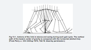
Below are some useful links to understanding the gait cycle:
http://courses.washington.edu/anatomy/KinesiologySyllabus/GaitPhasesKineticsKinematics.pdf
http://www.oandplibrary.org/alp/chap13-01.asp
Below are some useful links to understanding the gait cycle:
http://courses.washington.edu/anatomy/KinesiologySyllabus/GaitPhasesKineticsKinematics.pdf
http://www.oandplibrary.org/alp/chap13-01.asp
Tuesday, February 2, 2016
February 2, 2016
Today, our newest design for the foot sole section, including longer sides and a shorter sole that extends only to the heel, was printed. It will soon be tested for necessary adjustments. We are currently awaiting for our follow up meeting with Dr. Matt Caster this upcoming week. With his critiques and review, the necessary adjustments for our orthotic will made for our next prototype, that includes an elasticity function.
January 29, 2016
| Above is the CAD model of the new foot sole section with further adjustments. These adjustments include modifying the length of the sole, the height of the hinges, and the filleted edges. This new adjusted part will hopefully provide our project with the durability to endure the extreme stress on the 3-D printed part while walking. This product is designed at a right angle which brings great difficulty in 3-D printing. With extreme stress on this right angle, the correct durable plastic needs to be picked, with certainty, to ensure patients with a sturdy brace. |
Friday, January 29, 2016
January 29, 2016
From now, we need to finalize our foot sole design and then begin incorporating the elasticity function.
Monday, January 25, 2016
January 25, 2016
Our bands have arrived and work well to secure the calf section. We are now making adjustments to the design of our foot sole section (in or outside of the shoe) and their respective hinges (one or two degrees of motion, attached on the outside instead of having the braces "sandwiched" between them). Then, we will work on the elasticity function.
We have extruded the pegs directly from the calf section so that the foot sole section can be attached directly which will exclude the second degree of motion which the hinge created. When thinking about ways to incorporate the elasticity function which will life the toes up, a possibility would be to use a rubber "string" that can we wrapped around the peg and tightened if needed. It will serve to lift the user's toes up with the strength they need.
Friday, January 22, 2016
Thursday, January 21, 2016
January 21, 2016
Today, we redesigned the hinges. They now have a thinner profile and and longer pegs. Also, instead of connecting completely together, the pegs will be inserted through the other side and will be secured with a rubber end cap. The CAD Model for the new design can be seen below.
*We still need to figure out how to design the elasticity adjuster to lift the user's toes up as well as a way to secure the bottom foot sole section to the shoe. (A possible idea is to use attachments on either side of the calf section and connected to both of these will be "strong rubber bands" with a Velcro band at the end for adjustment, attached to both, that can be secured around the shoe and foot sole section. This design, however, will require this brace to exist on the exterior. Other options are possible as well with further exploration.)
*We still need to figure out how to design the elasticity adjuster to lift the user's toes up as well as a way to secure the bottom foot sole section to the shoe. (A possible idea is to use attachments on either side of the calf section and connected to both of these will be "strong rubber bands" with a Velcro band at the end for adjustment, attached to both, that can be secured around the shoe and foot sole section. This design, however, will require this brace to exist on the exterior. Other options are possible as well with further exploration.)
We will order these rubber end caps which have an outer diameter of 11 mm or 0.4 inches. The outside "lip" will keep the attachments secure. The design can be adjusted to fit these caps if they need to be used in the final design.
Wednesday, January 20, 2016
January 20, 2016
One of the hinges was printed (see below). Adjustments that need to be made include a thinner profile as well as a slightly longer pegs that secure themselves together and also allow for movement. Either that or the legs on the foot sole section can be elongated and the holes of both parts can connect together with an attachment piece to secure them.
Tuesday, January 19, 2016
January 19, 2016
Update: Our hinge will be printed shortly, and the bands will be ordered. This will complete our next prototype. Also, we have emailed Mr. Nye to set up a second meeting with our City As Our Campus mentor, Dr. Matt Caster. A meeting with Donny from Union Orthotics & Prosthetics will hopefully be scheduled soon as well.
We will instead be ordering these 18 x 2 inch cinch straps: http://www.amazon.com/18-Inch-Cinch-Straps-Pack/dp/B00VETJKRU/ref=sr_1_6?ie=UTF8&qid=1453231200&sr=8-6&keywords=cinch+straps
We will instead be ordering these 18 x 2 inch cinch straps: http://www.amazon.com/18-Inch-Cinch-Straps-Pack/dp/B00VETJKRU/ref=sr_1_6?ie=UTF8&qid=1453231200&sr=8-6&keywords=cinch+straps
Thursday, January 14, 2016
January 14, 2016
Today, we designed a hinge for this prototype. One will be printed so that we can make further adjustments before printing two. We will begin exploring different material options, design shapes, and whether we will be doing an outside-the-shoe brace or one that fits inside the shoe. A band will need to be ordered so that the calf section will be secure, and we will need to figure out a method of securing the bottom section. The product's general design will be perfected before allowing increased motor function through adjustable tension.
Also, a second meeting will be scheduled with our City As Our Campus Mentor to discuss our prototype and future plans.
Also, a second meeting will be scheduled with our City As Our Campus Mentor to discuss our prototype and future plans.
We hope to order this cinch strap (12 inch). These can be used to secure the calf section and maybe the foot sole section as well. https://www.securecableties.com/12-inch-black-cinch-strap-5-pack
Wednesday, January 13, 2016
Tuesday, January 12, 2016
January 12, 2016
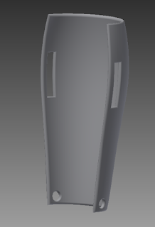
Today, we edited the CAD model for the calf section so that instead of a 180 degree rotation, it is a 195 degree rotation. This will hopefully allow the holes at the bottom to line up more parallel. We also edited the foot sole attachment so that the two pieces fit closer together. These will be printed again, and then we will design the attachment of the two pieces and the function that lifts the user's toes up.


Friday, January 8, 2016
January 8, 2016
The products that are being designed now for this issue of drop-foot restrict the client's foot and calf to 90 degrees. This inhibits them to walk completely naturally, and often, the individual actually has the strength to push off with their foot sole in order to propel themselves forward (this requires a greater than 90 degree angle). Our design will not restrict this movement, but will use an elastic adjustment system to push the individual's toes up (making the angle less than 90 degrees) after they have lifted their foot up in the process of walking.
Thursday, January 7, 2016
January 7, 2016
The second part of our brace (the design which goes outside of the shoe) has been printed and seems to fit nicely with the calf section. We will continue to make adjustments.
Wednesday, January 6, 2016
January 6, 2016
Today while designing the foot sole part of our brace, I came up with the idea to possibly be able to get rid of the sole that goes in the shoe altogether. The calf part of the brace can instead be attached to any shoe and still provide the user with the same assistance because now the shoe itself is acting as the sole that is attached to the rest of the brace. Also this way, the costs can be cut because the majority of the product is the one section which is 3D printed. We will explore this idea and most likely design two products, one with the sole that fits inside the shoe and one in which the shoe is used as the "sole" itself (this will require a semi-custom/adjustable attachment to work with different types of shoes/sizes which will need to be made out of durable material and a strap to secure the shoe). After we have concrete prototypes for each, we will begin exploring the actual functionality and how our elastic-adjustment will work.
-Naomi
-Naomi
 |
| This will be printed |
Monday, January 4, 2016
January 4, 2016
We started off the first class of the new year creating an abstract for our AFO. We gave a general synopsis of the device including such knowledge as the prototyping process, the device's goal, and the future of our research/design process. The official abstract can be viewed in the Design Process tab or at this following link http://mobilitycures2016.blogspot.com/p/design-process.html.
Subscribe to:
Comments (Atom)


