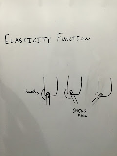
- an elasticity cable connecting from the calf section to the bottom/foot section (on the outside) that doesn’t have resistance when foot is forward but then snaps into position when foot is back, tension will break during swing phase of the gait cycle
Wednesday, February 24, 2016
February 24, 2016
We adjusted the attachment so that the spline is approximately 2 inches shorter. Currently, without the adjustment, the attachment will not fit into the shoe correctly. We will continue to test the prototype and make further corrections. We will also scan Naomi's foot and create an insole from the scan using MeshMixer which we will then join with the attachments to make one solid (this will be the second part of the brace). After we complete the brace structure prototype, we will add on the elasticity function (our plans for this can be found under "City As Our Campus Mentor Info"):
Monday, February 22, 2016
February 22, 2016
Today, we began designing the pieces to attach the insole to the calf section. We will use this attachment, created in Inventor, and transfer it into MeshMixer to conjoin the sections.
We will perfect this piece and then decide if we will need just one or two of these pieces, taking stability into account. We can use this one to test on the outside of the brace on the left foot or the inside of the brace on the right foot. If we decide we want an attachment on both sides of the foot, we will need to either mirror this part or construct a separate one. Then, with Boolean Union, we can join the soon-to-be-created insole with the attachment into one solid. After we finish this section of the brace, we will work on the elasticity function.
Thursday, February 18, 2016
February 18, 2016
Today, we visited TechShop, http://www.techshop.ws, to learn how to use MeshMixer. We will be using MeshMixer to construct our custom insole, and then to incorporate the use of Inventor. We will use Inventor in order to construct the sides of the brace, that connect the calve section of the brace to the sole. After we complete this, we will work on the elasticity function. Rough sketches for both of these designs can be found below. We will construct the custom insole using MeshMixer and the sides using Inventor, then combine them into one solid object in MeshMixer with the Boolean Union function. We are also expecting to visit TechShop once again to improve our custom insole and to also improve our prototype as a whole before sharing it on March 8th, at TechShop.
Wednesday, February 10, 2016
February 10, 2016
Today we met with our City As Our Campus mentor, Dr. Matt Caster, for the second time. Notes on our meeting with him can be found in the "City As Our Campus Mentor Info" tab. We discussed designing our brace to fit in the shoe, where to attach the hinges (in the center of the insole), creating a custom insole, and designing our elasticity function (an elastic band to attach to the calf section and hinge around the front, creating tension when the foot is back in order to pull it through).
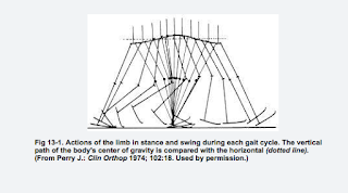
Below are some useful links to understanding the gait cycle:
http://courses.washington.edu/anatomy/KinesiologySyllabus/GaitPhasesKineticsKinematics.pdf
http://www.oandplibrary.org/alp/chap13-01.asp
Below are some useful links to understanding the gait cycle:
http://courses.washington.edu/anatomy/KinesiologySyllabus/GaitPhasesKineticsKinematics.pdf
http://www.oandplibrary.org/alp/chap13-01.asp
Tuesday, February 2, 2016
February 2, 2016
Today, our newest design for the foot sole section, including longer sides and a shorter sole that extends only to the heel, was printed. It will soon be tested for necessary adjustments. We are currently awaiting for our follow up meeting with Dr. Matt Caster this upcoming week. With his critiques and review, the necessary adjustments for our orthotic will made for our next prototype, that includes an elasticity function.
January 29, 2016
| Above is the CAD model of the new foot sole section with further adjustments. These adjustments include modifying the length of the sole, the height of the hinges, and the filleted edges. This new adjusted part will hopefully provide our project with the durability to endure the extreme stress on the 3-D printed part while walking. This product is designed at a right angle which brings great difficulty in 3-D printing. With extreme stress on this right angle, the correct durable plastic needs to be picked, with certainty, to ensure patients with a sturdy brace. |
Subscribe to:
Comments (Atom)


